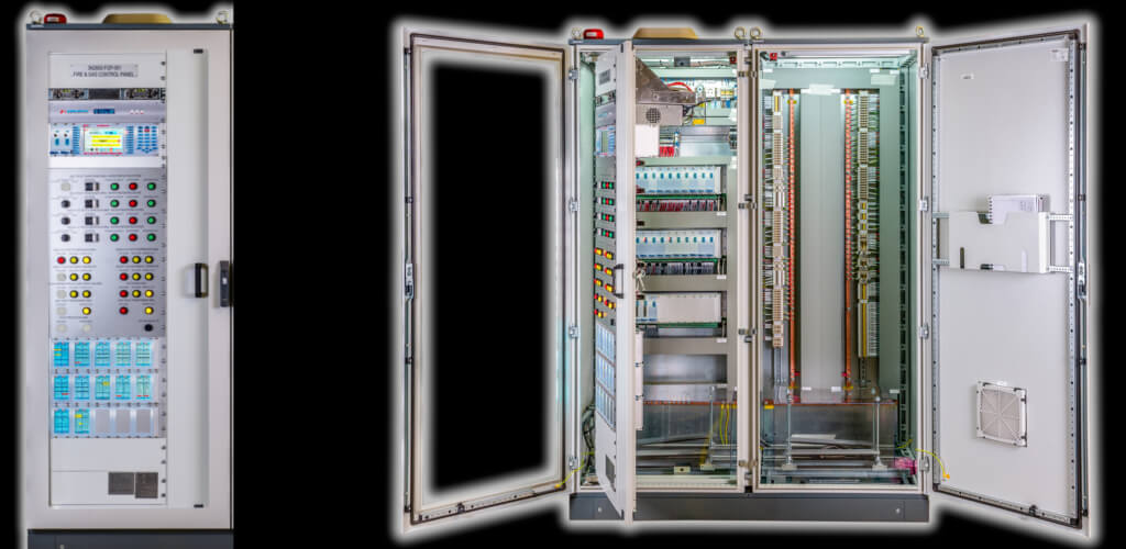
control unit exfire360
Here is the evolution of the species!
EXFIRE360 control unit Fire & Gas Functional safety SIL and Remote fire-fighting management
The evolution of technology and the growing performance requirements of automatic fire detection and extinguishing systems; have introduced two new features of the fire alarm control panels: the Sil functional safety of the systems and the remote management of the systems. SV’s EXFIRE360 Fire & Gas modular control panel has been designed to offer customers both functions, as well as guaranteeing the CPD certification of the product according to the standards EN 54-2, EN 54-4 and EN 12094-1, EN 60079-29 -1
RESEARCH AND DEVELOPMENT
In 2010 the latest generation EXFIRE360 Fire & Gas plant was born. The initial specifications of the plant for its construction were recovered and written after a long experience in the national and international field, of system applications with various plants of different brands, where SV has made a virtue of a necessity, developing research in the sector Fire prevention in the construction and production of control units for Fire & Gas, Flame, fire extinguishing of the EXFIRE360 series. exfire360 control unit
THE EVOLUTION
A new concept of Information and Mitigation that takes place between the user and the engineered system and protected by a complete interaction with remote supervision. The new EXFIRE360 Fire & Gas control unit is a programmable modular unit, extremely versatile and capable of carrying out integrated fire prevention functions, technological alarm management and serial management of various protocols.
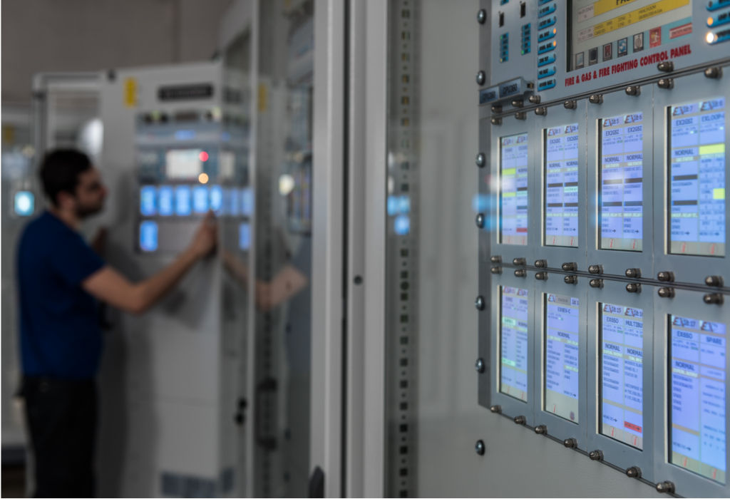
The basic version of the EXFIRE360 Fire & Gas modular control panel with 19 “rack system is composed of a Master LCD front panel, 18-key keyboard for accessing the system, 8” LCD Touch Screen display (16 remote LCDs via redundant 485 line) to view the general information and the main Fire & Gas general anomaly conditions, shutdown, disabling and exclusion and 4.3 ”Touch Screen mini display containing the information of the boards.
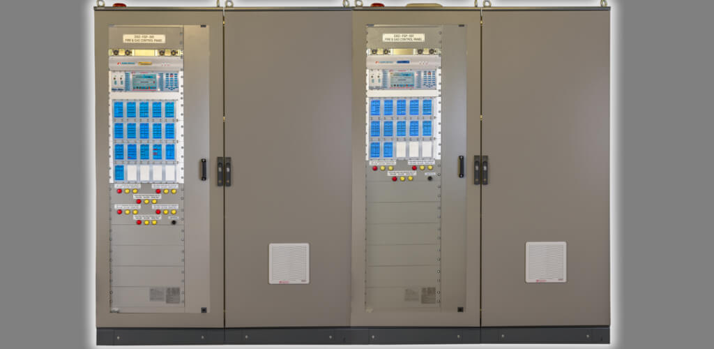
The EXFIRE360 control unit characterized by an IP55 front opening cabinet with predetermined dimensions of 2000 (h) x 800 (W) x 800 (D) mm.
The cabinet as shown in the side figure and complete with 100mm plinth, consists of a basic rack for the CPU and front panel, card rack; Front panel holder racks Both racks mounted on the front door of the panel and rotate with it, freeing access to the connection and power supply area.
The connections made by means of special terminal blocks applicable on a DIN bar already prepared and placed inside the panel.
The level of parameterization of the control units will be perfectly modular and simple to use. The instructions for defining and customizing the parameters will be made available to system maintenance personnel.
The compilation program will be supplied on request on disk and can be installed on a PC. The program will then be transferred to the control panel via the serial line.
Inside the control panel, the configuration program will be contained on non-volatile memory; this means that it will not be canceled even in the event of a power failure and with the batteries disconnected.
The control unit is of the modular type; consisting of a 19-inch rack in which the various detection and / or extinguishing and / or technological control boards can be inserted.
The cards inserted from the front in the internal part of the control unit, while the displays with redundant communication RS-485 will be positioned at the front. In the event of a fault, it will therefore be possible to replace the cards quickly without having to operate on the connection terminal blocks.
All the support terminal blocks coming from the boards are accessible from the rear panel of the switchboard; external side, and engineered for access to the terminal board from the outside; opening the rear door of the panel.
The control unit has specialized boards to control analog / addressed type sensors; conventional cards with collective lines and analog and digital input and output management cards.
The shutdown managed by specialized boards which have the task, among other things, of verifying the discharge; checking the switching of the pressure switch to signal the system’s non-response after an extinguishing command.
On all boards there are touch screen control buttons for various functions; from the visualization of the card diagnostics, to the visualization of absorptions of the operating lines; events (with access levels under password) to the extinction command.
The control panel checks the efficiency of the connections of all the detection lines; it also controls the system used with the sole exclusion of the relay outputs.
The control panel is able to communicate with a remote supervision system; both through lines dedicated to remote surveillance and on a switched telephone line, with automatic call in the event of an alarm. This function allows you to connect several control units to a remote remote management system; using a single telephone line (two in the case of a redundant system).
- CPU operation 1
- CPU 2 operation
- CanBus trend
- Alarm conditions
- Conditions of Anomaly
- Status of Excluded
- Normal conditions
- Out of service status
- Input Activation Conditions
- Output activation status
- OC Activation Conditions
- Activation conditions of the channel protections
- Information on the feeding of each card
- Consumption information for each single supervised input / output channel
- Indication of the resistance value acquired by the supervised input / output channel
- Information Operating temperatures for each board and environmental
- Operating humidity indication for each board and environmental
- Information of all the Hardware blocks for each single board
- Indication of the various Alarm / Anomaly settings of the boards
- Information of historical events up to 2000 color graphics events

